PDF files :
Surge Protector
(480k)
Standard
Straight Modules
Standard Curve Modules
Wide Radius Curve Modules
Transformer Platform
Web page:
You won't find the word defined in Webster's Dictionary. And
if you ask three or four people at a train meet you'll probably get three or
four different replies all trying to define or defend their understanding of the
term Hi-rail. It's not so easy to give a clear definition because the term is
very subjective, each person having his own interpretation of what the term
means. I think the real obstacle in coming up with a generally accepted
definition is that there are those of us who will try to defend or make
apologies for what it is not. There are those who would tell us in no uncertain
terms that we are not O Scale model train hobbyist! The way I see it, strictly
speaking, the technically universally accepted definition of O Scale is that it
represents modeling scaled down from the prototype to a 1/4 inch representing a
prototypical foot.
Beyond that technical measurement, any further definition of
O Scale is a person's personal elaboration. A renown modeler of O Scale, John G.
Macleod, last year wrote in 48/ft. O Scale News, an article entitled, "What
Is An O Scale Railroad?" He maintains that O Scale encompasses a mass of
different identities, including Proto:48, Hi-Rail, Scale-plate, Semi-fine,
Outside 3rd Rail, Center 3rd Rail and all kinds of numerical combinations and
concludes that O Scale is all of these! He goes on to say, "All approaches
are equally valid." Who's to say you can't run an O Scale train on three
rails? After all I've seen three rail prototype track albeit it was laid in that
manner so the railroad could run both standard and narrow gauge trains on the
same rails. What about the New York City subways and interurban trains that use
a third rail for their electrical power. And there are O Scale layouts that use
an outside third rail for their power. One of the oldest and most impressive O
Scale layouts in America using an outside third rail is set up each holiday
season at the Cincinnati Gas and Electric Company.
As the owner and operator of the JL/ATSF RAILWAY and
co-author of the book Realistic Railroading with Toy Trains, I'd like to give
you my interpretation of the term Hi rail. Unlike other model railroaders, Hi-railers have the distinction of coming from a toy train heritage almost 100
years old ‹ Lionel Trains. In fact, we know that Mr. Cowan almost 60 years ago
was thinking about prototype equipment when he produced his first 700E Hudson
locomotive. However, very few references were made that long ago or even more
recently to the term Hi-railer. From my research, the only early use of the term
Hirail that I could find was a somewhat derogatory label used by O scalers.
Tinplate track is about a quarter of an inch higher than scale track and has
three rails thus the term Hi-rail. There are probably other early references but
the antecedent of the term is no longer important. In the 1990's it has become
identified with those train operators that would like to pattern their layouts
and trains on the prototype.
To get to the bottom of its meaning we need to briefly review
some of the confusing definitions usually made by persons that are not Hi-railers. Whether Hi-rail trains are to be called toy, model or miniature
doesn't make much difference. If one were to ask an O gauge hobbyist the
question what is Hi-rail, he might say, "oh a Hi-railer runs big
locomotives on three rail track." Or say, "he's a tinplate Lionel
Train operator who likes to run long trains." If we were to ask a serious
Lionel Train collector who may also occasionally run his trains, he might say,
"Gee I don't know, he's some guy that's pretending his trains are more
realistic than mine and therefore better!" or "Hi-railers are very
serious about their trains and don't have much fun." Which of these
comments holds any truth? Each of these answers probably holds some truth .
Hi-railers are not a superior or snobbish group of hobbyist.
We simply want our trains to appear more realistic or prototypical. We want our
entire layout to appear as realistic as possible. If a Hi-railer wants to run,
let us say, an O Scale Union Pacific turbine with 20 scale UP boxcars, but on a
"traditional" layout, who's to say he can't call himself a Hi-railer?
I'll give you an innocent example of what I did to my Lionel
Trains when I was sixteen years old. In 1952, my brother and I bought our first
Lionel locomotive, a Hudson Lionel 773. Realizing what a good choice we had
made, we also realized that the name "Lionel Lines" on the tender and
773 on the cab were totally fictitious. From the Atchison, Topeka and Santa Fe
Railway System, we obtained a book entitled "Santa Fe Car and Locomotive
Plans for Model Railroaders" published by Kalmbach Publications. Looking
through the book, we found a 4-6-4 that we thought at the time looked pretty
much like our Lionel Hudson, so we proceeded to remove the "Lionel
Lines" and 773 and replaced them with the number 3462 and A.T.&S.F. on
the cab. That was a lot more realistic. I've never had any regrets about
changing the name and number even when many years later I began to realize what
a collector's trophy this locomotive had become. Looking back over forty years I
now realize that I was a pioneer Hi-railer seeking realism for my trains.
Realism takes many levels and each Hi-railer will determine for himself a level
he'd like to attain.
There are several levels in attaining a prototypical layout
and each of us has our own expectation. Webster's defines the word prototype as,
"an original model on which something is patterned" or perhaps another
way of saying patterned on the "real thing." See how this Prototype
Pyramid fits your Hi-rail objectives. The basic step is to operate railroad
equipment as close to 1/4 inch scale as possible. The next step up the pyramid
is "Generic Interest." What will be your mixture of prototype
railroads and types of equipment? Then comes the decision about "Era,"
motive power, rolling stock, buildings, signs, cars trucks, people are carefully
selected to represent a particular time period, past or present. This leads us
up the pyramid again to the "Locale of Railroad," the particular
geographical depiction of a specific area where this railroad operates and
includes the location, topography and season of the year. At the very top of the
pyramid is a choice to operate a "Specific Railroad" along with all of
the other steps of the pyramid. This entails repainting, re-lettering, and
weathering the locomotives and rolling stock. One may also operate rolling stock
that is individually numbered and finally operating the trains in a prototypical
manner. If all of these steps were followed, then for sure we'd all agree that
it's very prototypical and much different from a tinplate toy layout.
Of course there are some given restraints that an O gauge Hi-railer
must contend with namely operating on three rail track. However, except for the
huge couplers and the fact that our O gauge train wheels are designed to best
operate on three rail tubular track there aren't really any other restraints
preventing a Hi-railer from operating an O Scale railroad. Only for the
"dye-in-the-wool" O scale modeler, who gives Hi-railers a
condescending smile and says under his breath, that while we may think we are
operating in O scale its impossible because we are really tinplate toy train
operators. But who needs their acceptance and approval? We need not give them
the time of day! By the way, the word tinplate has nothing to do with our
Hi-rail model trains. The word is an archaic reference to what was and unless
one is using Lionel type tubular track, you won't find any tinplate on a Hi-rail
layout. John Macleod concluded in his article from 48/ft. O Scale News,
"Personalize your layout to suit your priorities. My version of O Scale is
no better or worse than yours or his or hers, what matters is how well your
version suits you."
Because a few manufacturers of model trains decided that
there seemed to be a growing trend in the O gauge Hi-rail market they began to
cater to Hi-rail with more and more prototypical products. And I don't mean only
manufacturers of motive power and rolling stock but of everything we'd like to
see on our layouts. A Hi-railer not only wants to be as close to 1/4 inch scale
as possible for his trains but also his model town, cars, trucks, people all
other details. If he or she does not model these items themselves they can
be carefully selected from the marketplace as close to scale as they can find.
Even, later discarding certain items for more prototypical ones as they become
available. Tony Koester wrote in the revered scale model magazine "Model
Railroader" as it pertains to HO modelers seeking greater realism, that
this trend toward realism has grown to embrace structures and even operating
practices. This applies as well to Hi-railers. Does being a Hi-railer mean that
we no longer want Lionel accessories and buildings? Not necessarily, many of the
Lionel plastic building kits, particular the classic ones like the Grain
Elevator #820K, the Rico Station #825K, the Engine House #835K and the
Passenger/Freight Station #83K, are all nearly perfect scale and with some
customizing, fit perfectly with scale equipment. When it comes to the Lionel
operating accessories, that's a more complex subject. The operating accessories
are toys and the rolling stock that's usually associated with these accessories
are not in any way scale. So maybe this is where we bend the rules of scale. A
customizing job does improve their appearance on our layouts and besides who
doesn't get a kick out of watching an operating Saw Mill or Icing Car in action?
One operating accessory that comes close to the prototype is the Water Tower
#138, which is back again in the Lionel catalog.
A final area in which Lionel Trains has particularly helped
Hi-railers achieve their objective has been with their sound systems. Lionel
aims at producing absolutely prototypical sound for their locomotives. Also
Lionel's power control system with "Train Master" Command Control and
its remote Cab-1 control provides added realism and flexibility for Hi-rail
operators.
Hi-rail operation and layouts are gaining a lot of
"steam". As the Hi-rail manufacturer provides more and more product
for us we are challenged to use their scale equipment in building and operating
more realistic and prototypical layouts.
Joe Lesser
Written for Classic Toy Trains
May, 1997
D.C. Area Independent HiRailers
Module Building Techniques and Notes
Edited by Frank E. Qualls, © DC Area Independent HiRailers, May, 1998
Since I started building modules using the plans of The
Independent HiRailers, I have developed some building techniques and made
some construction notes. I think these techniques and notes are worth sharing
with others who are starting to build their modules.
The first thing I did to improve my modules was upgrading
all of the wire specifications from 16 to 14-gauge wire. The reason for using
the 14-gauge wire is to ensure that there is no locomotive slow down due to
the heavy current requirements of running multiple locomotives, with their
four or more motors operating, as well as lighted passenger cars. Stranded
14-gauge copper wire, which comes in various colors, is available in the
electrical department at Home Depot or other national hardware chain stores.
The Gargraves track we use does not have a common ground
between its two outer rails. On all full-length pieces of Gargraves track used
on the modules solder a stranded 16-gauge jumper wire to the outer
rails between the twelfth and thirteenth track ties. Additional jumper wires
are not required on any other short pieces of track used on the module since
they are connected into a piece of track which has a jumper wire installed.
Using the jumper wire on the Gargraves track helps to facilitate the usage of
common ground wiring on the module and the modular layout.
Proper construction of the bench work for the modules is
very important. Sanding the wood flush on all sides gives a fine finished look
to the module’s bench work. Since a bridge track is not used in this module
design it’s important that the module’s bench work mates tightly together.
The technique used to achieve this is to set the modules up on their legs
prior to laying the track. Then butt the ends of the modules together, secure
them with C-clamps then check for a tight fit between the module decks. If
required, use a belt sander with a #50 or #80 grit belt and sand each
end of the modules to ensure a tight fit. Note: When doing this it is
important to check for the high spots that are preventing a tight fit on each
end and sand them down. A power or manual planer can also be used for
this.
After the bench work is sanded, install the roadbed, then
spray paint the module deck and roadbed flat black. Flat black latex paint,
available from Home Depot, can also be used for painting the module deck. The
purpose for painting is because scenery material and ballast will be lost
during transport of the modules. The black paint prevents bare wood or cork
from showing on the module if this occurs.
After the module deck and roadbed have been painted flat
black, you will start to lay your track. To facilitate the connecting of the
wires to the track, holes are drilled through the deck of the module. Prior to
drilling these holes, cut approximately a 3/8” by 3/8” square hole in the
roadbed beneath each rail where a wire is attached. This makes drilling the
holes through the deck easier. Normally, the power and ground wires are
connected to the tracks between the fourth and fifth track ties. Mainline
tracks one and two will have three holes drilled under their rails and track
three will have only two holes drilled.
Typically, when beginning to lay track on a module, it’s
customary to start with a full 37-inch piece of Gargraves track. There are
some additional track preparations required. Since all wires are soldered
to the track from underneath the module deck, all three rails need tinning
with solder. The center rail requires using a Dremel tool with a grinding
stone attachment or either a hand file to remove the blackening to aid in the
adhesion of the solder to its rail. The pre-tinned power feed wire for each
mainline track is then soldered to the center rail after the blackening is
removed. Please use a wire of sufficient length to reach the barrier strip for
connecting after terminating it with a spade or ring lug.
These modules use common ground wiring. The main ground
wire for the module is soldered to the outside rail of track number one. This
wire connects to the main ground on the module barrier strip. Along with the
power feed on the center rail another ten-inch long ground wire is attached to
the other ground rail on track number one. All three of these wires are then
fed through the holes on top of the deck. The second ground wire on track
number one is then fed up through the hole beneath track number two for
connecting to its ground rail closest to track number one. Track number two’s
other ground rail then receives a ten-inch long ground wire which is fed
through the hole on top and subsequently gets fed up to track number three and
connected to its ground rail. Once all power and ground wires are connected to
their respective rails, align each 37-inch piece of track to be flush with the
edge of the module and spaced as per the specifications. Then pre-drill the
track ties and screw the 37-inch piece of track to the module deck. Note:
This technique of connecting ground wires eliminates trying to connect four
ground wires to one barrier strip ground terminal.
The next step required is to cut a piece of track 12-inches
long. This piece of track fits into the 37-inch piece and completes the
48-inch length of track required for the module. There will be some track
overhanging the end of the module. Secure the 12-inch piece of track to the
module deck with screws. Gently tap the overhanging piece of track to ensure
that the track pins of the 12-inch piece of track are seated tightly. Next,
locate a 2-inch by 2-inch by ½-inch thick or similar flat piece of metal,
which you will use as a gauge and lay it flush against the opposite end of the
module bench work and track. Gently tap the end of the overhanging piece of
track to ensure that the end of the 37-inch piece of track is flush with the
end of the module.
Cut the overhanging piece of track one quarter of an
inch from the end of the module using a Dremel fiberglass cutoff wheel.
The quarter inch of track remaining requires using a hand file to adjust this
track flush with the end of module. Filing allows you to control how much
track material you remove and alleviates the problem of cutting the track too
short. Use straight and even filing strokes and the flat piece of metal as a
gauge. Check often with your flat metal gauge positioned flush against the
module bench work and track to ensure when the track is flush with the end of
the module.
Straight track is critical to smooth operating of the
trains on our modules. When all the modules are connected, the three mainline
rails should be as straight as the rails on a prototype railroad. This is
achievable using a four-foot metal ruler available from Home Depot or other
national hardware chain stores. Using the ruler as a straight edge, position
it in the track groove just below the track railhead on the outer rails. Once
the ruler is in position, loosen the track screws and pull the track into
straight alignment against the ruler. Please make sure that you maintain the
standard 4 ¼-inch spacing between the track’s center rails. After
completion of this procedure, your track should be as straight as an arrow!
After all tracks are secured to the module deck, terminate
each wire with either a spade or ring lug. If you are not using color-coded
wire, then identify each wire with adhesive number markers and then connect
them to their proper terminal on the barrier strip. Please consider using #1
for Track 1, #2 for Track 2, … and #4 for Ground, #5 Accessories, etc. The
next step is to perform continuity checks to ensure that your wiring is
correct. This can easily be done using a volt-ohm meter set for measuring
ohms. Using wire staples tack down any long lengths of track wires to the
bottom of the module deck and use wire tie wraps accordingly. The final step
is to fill in the holes the wires pass through from the bottom of the module
using either RTV or caulking material. The purpose for doing this prevents the
ballast from falling through the holes of the module when it’s applied.
Prior to laying your ballast ensure that the track ties at
each end of the module for each track is flush against the edge. Note: Failure
to do this step will result in a gap between the track rails and the module
deck. This gap can cause the track to become snagged on objects and result in
damage to the rails.
Frank E. Qualls © reserves all rights to this document.
11/98
Top of Page
Module Specifications
DC Area
Independent HiRailers
Module Specifications and Information
To present a uniform but distinguished modular display,
participants are encouraged to build their modules to the following Independent
HiRailers specifications:
Stain the module sides, ends, and legs with Minwax
number 2716 Dark Walnut stain. This product is available from Home Depot
in small cans and is easily applied with an old rag or paintbrush.
Paint the cork roadbed before adding track ballast. With
the constant transporting of modules, you will lose some of the track ballast.
Then the unpainted brown cork roadbed becomes visible. Independent
HiRailers who use a 50-50-ballast mix have painted the cork roadbed on their
modules black. I have done the same and find this color blends very well and
its not noticeable when some track ballast is lost.
Paint the inside and outside of both Gargraves track outer
rails with Floquil number 110070 Roof Brown paint. This paint
color is the closest that resembles the color of rust on the rails. Before
painting your rails wipe the grooved side of the rail below the railhead with
an alcohol soaked Q-tip to remove the oil residue. A number 4 artist’s
paintbrush easily fits in the groove and helps make painting the rails easy.
Ballast the track with a 50-50 mix of Woodland Scenics Coarse
Gray number B89 and Coarse Cinders number B90. For
instance on my modules for ballast I chose to use O Scale Limestone and
Coal Ballast in a 50-50 mix which I purchased from Jeff Green at
Kelster Interprises, 12463 Atwood Pl., Fishers IN. 46038, 317-595-0831. This
product is also available in Dark Gray and costs as follows: 1-25
pounds at $1.25 per pound plus shipping and 26 pounds or more
the cost is $1.00 per pound plus shipping. If you decide to use O Scale
ballast call Jeff Green and give him the total track footage you are going to
ballast and he will calculate how much O Scale ballast you need. Note: I
find this product is very cost effective. Woodland Scenics costs $2.75 for an
eight-ounce bag!
Scenery on your modules is a personal choice to which the
Independent HiRailers encourage use of your imagination, but remain within the
High Rail and O Scale theme of model railroading.
These are current Independent HiRailers specifications to
keep in mind when constructing your modules.
For more information contact Frank E. Qualls
at fequalls@aol.com
Top of Page
Replacement Power Connectors
For
Independent HiRailers Modules
Specified
and compiled by Frank E. Qualls, DC Area Independent HiRailers, October, 2002.
All of the current Independent HiRailers Module
drawings show a Radio Shack, Molex type connector. Molex, the OEM manufacturer
of our connectors decided to stop producing them in 1995. Now all of the bulk supply of those connectors at Radio Shack
Unlimited has been exhausted. Please find below a new replacement connector
that has been specified and is readily available to all who use the
Independent HiRailers module drawings.
The
replacement connector I have selected has the same six-pin configuration as
our original Molex connector. It also is a Molex type connector rated at
nine-amperes per circuit. I have
successfully used these connectors on my multiple 8-module set train yard.
The yard track’s wiring harness uses these type connectors on the
modules interconnecting pigtails. The
DC Area Independent HiRailers has since started using these connectors on our
mainline harnesses on all new modules built which have dioramas consisting of
two or more modules. We continue
to use the original Molex connectors on the ends of these modules to mate to
all other modules with the same original connectors.
We have been doing this successfully for the last five years without
any overloads, discoloration or melting the Molex plastic connector shell
rated at nine-amperes. We also use this same connector for any other
application on multiple module sets that require multiple wiring harnesses.
Therefore, after consultation with other Independent HiRailers module
group coordinators I am specifying the below Independent HiRailers “Replacement
Connector.”
The below
listed parts are marketed and sold as Molex/Waldom Power Connectors.
These connectors are Molex OEM .093” Diameter Connectors with a
per circuit current rating of 9 amperes. They are available at Radio Shack
and many other electronics parts dealers.
Listed below are the Radio Shack part numbers and four mail order
electronics suppliers who have a good track record of stocking these parts and
whose prices are competitive. Please
contact each of the below listed electronics suppliers and request their
latest parts catalogue.
Digi-Key Corporation
701 Brooks Ave. South
Thief River Falls, MN 56701-0677
1-800-344-4539
Name Molex OEM P/N
Digi-Key #
Price
Plug/Male
03-09-2061
WM1317-ND
1 @ .62, 10 @5.09
Receptacle/Female
03-09-1061
WM1316-ND
Same as above.
Male Pin
02-09-2103
WM1100-ND
10 @ .74, 100 @ 5.94
Female Pin
02-09-1104
WM1101-ND
Same as above.
The
above parts are also available from:
Mouser Electronics
Newark Electronics Allied
Electronics
www.mouser.com
www.newark.com
www.alliedelec.com
800-346-6873
800-463-9275
800-433-5700
Radio Shack
Name
RS Part #
Price
Plug/Male
274-226
1.39
Receptacle/Female
274-236
1.39
Note: The Radio Shack parts were shown in their
2000 catalogue but they may also be discontinued.
So please use the information above from the other electronic
suppliers. The best source for
these parts is Digi-Key.
Top of Page
HiRail Ballast Technique
By
Frank E. Qualls
When displaying my HiRail train modules in public I have
received many compliments on the track ballast. My mentor, Steve Horvath,
founder of the Independent HiRailers taught me the ballast laying technique I
will detail below.
To begin your track ballast project you want to use a high
quality ballast such as Woodland Scenics, Coarse Gray # B89 and Coarse Cinders
# B90. I chose to use O Scale Limestone and Coal Ballast from Kelster
Interprises. (Further information on Kelster is listed in the Independent
HiRailers Module Specifications.) Either of these ballast products will work
just fine. The Independent HiRailers ballast specifications call for a 50-50
mix of gray and cinders.
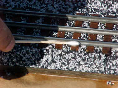
There are many devices one can use for laying ballast.
Normally, I utilize a small plastic cup as a ballast dispenser. I squeeze the
top of the cup to form a U-shape to control the flow of the ballast. It is
spread onto the track ties between the rails two thirds of the length of the
track. Next, spread the ballast the full length of the outside of the track
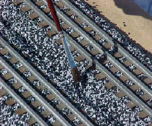
covering the tie ends and tapered roadbed. Using your index and second finger,
start in the middle of the track spreading the ballast on each side of the
center rail by pushing it along the full length of the track. As you do this,
some of the ballast will fall outside of the track on top of the ballast
already on the tie ends. As the ballast continues being pushed along by your
fingers, the spaces between the ties are filled. The excess ballast continues
moving along the tops of the ties filling in between the ties where no ballast
was initially spread. Repeat this procedure until the entire track where
ballast is laid has been spread to the opposite end. Using this technique you
should get to the end of the track with excess ballast or having to add a
little to finish the job.
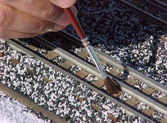
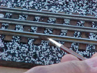
Any ballast remaining on top of the ties can be gently
brushed between them with a small ¼” artists paintbrush. The outside
of the track requires using the paintbrush to remove the ballast from the top
of the ties. As you brush the ballast away ensure that it is level between the
ties and at the ends of the ties. Taper the ballast away from the ties and
slope it to the contour of the roadbed to create a swell between the tracks.
(Note: More ballast may be required for tapering and to aid in the making of
the swell.) Once you have completed this on each side of the track, you are
ready to move on to the next track. Upon completing all three mainlines and
any siding tracks, you are ready to secure the ballast.
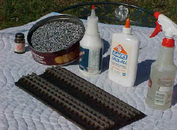
Materials for this project. Floquil Roof Brown Paint, Ballast, Glue water
mixture, Glue, Wet water sprayer and track.
Applying the track ballast.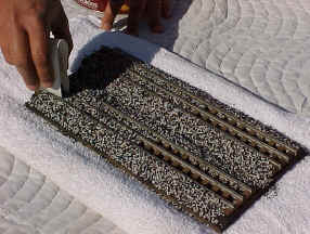
The two finger ballast spreading technique.
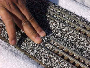
Brushing ballast off of the ties.
Creating a swell between the tracks.
Photos by Randolph Co.
Top of Page
Securing Your Ballast
By
Frank E. Qualls
Before gluing your ballast, it is very important that the
ballast is level between the ties and outside the rails and at the tie ends.
This ensures that cohesive bonding occurs between the ballast particles and
all sides of the track ties. It also prevents the flaking off of the ballast
after the glue cures.
Prepare a spray bottle capable of mist spraying a solution
consisting of water and a few drops of liquid dish detergent. This solution is
called “Wet Water”.
Using the “Wet Water” solution spray the ballast
well prior to applying the glue mixture to prevent ballast “Washout”.
Mix up a strong 50-50 White Glue and warm water mixture
with a few drops of liquid dish detergent in a squeeze bottle with a spout.
Shake this solution vigorously for it to blend well so that it flows smooth
and freely. This solution should not be thick and stringy.
Begin gently drenching the ballast between the ties on each
side of the center rail moving backward and forward over a 9 to 12-inch area. (Note:
Do this gently. Do not splash the glue mixture onto the ballast. This will
only serve to dislodge it. Take your time until you get a feel for how the
glue mixture is flowing onto the ballast.) You should see the white glue
mixture leaching into the ballast at the tie ends outside the rails. When this
is visible, begin to soak the mixture on top of the tie ends on both sides of
the track.
After you see the mixture leaching into the tapered ballast
on the roadbed, begin to soak that area until you see the white glue mixture
rise to the top of the ballast. Once you see the white glue mixture run onto
bare plywood outside track one or track three or rise to the top of the swell,
you know that enough glue has been applied. When this occurs continue to move
further down the track repeating the above steps. Be sure to continue to use
the “Wet Water” mist generously as you move along the length of the
track prior to applying the glue mixture.
Repeat the above procedures for the ballast on each track.
36-hours after the glue cures the ballast should be rock
hard and there will not be any flaking of the tie ends, tapered roadbed or the
swell between the tracks. This technique has been used successfully on the
twenty-three modules that I own. Have fun as you ballast your track using
these techniques on your modular or permanent layout.
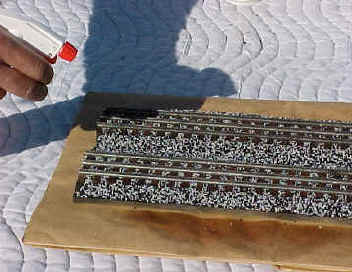
Wet water application.
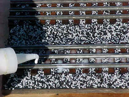
50-50 Water and Glue application.
Cleaning track before painting.
Floquil Roof Brown paint application to track.
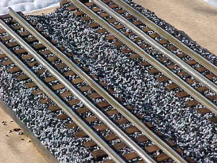
Completed job on the tracks.
Photos by Randolph Co.
Top of Page
Slowdown Circuit
Upon seeing the “Slowdown Circuit” drawing on the HiRail
egroups list posted by Matt Jackson of the Angels Gate HiRailers. I (Frank E.
Qualls) contacted Matt to inquire about posting his circuit and edited text on
this site. After Matt agreed to the editing I had done to his text, the
HiRailers Unlimited is now pleased to present this circuit drawing and
accompanying instructional text for all HiRailers.
Constant 1.5 volt Headlight
DC Can Motor Slowdown Circuit for 3-Rail
By
Matt Jackson
Angels Gate HiRailers
The following circuit I will describe below is based on a
minimum rating four-ampere bridge rectifier modified for reducing the voltage
applied to DC Can motors in three-rail trains.
A bridge rectifier is an electronic device, which has four
electrical terminals and four regular diodes arranged as depicted in the
drawing below. Each of it’s terminals is individually identified as either
Plus or (+), Minus or (-), and two labeled as AC or (~). To accomplish what I
am proposing as a “Slowdown Circuit” will require electrically tying the
Plus and Minus terminals of the bridge rectifier together with a jumper wire.
What this basically does is electrically rearrange the diodes into two pairs
for bi-directional DC current flow (+/-) and results in a 1.4 volt reduction
at the output.
Think of a diode as a switch that turns on at .7-volts. The
first diode in the pair does not switch on (or conduct) until the .7-volt
threshold is reached, but the second diode in series is still “off.” An
additional .7-volts is required to switch on the second diode in series for a
total of 1.4-volts before current flows through both of them. Then the
required switching voltage reduces the output. For further voltage reduction
you could install a second modified bridge rectifier for a drop of 2.8-volts.
One bridge rectifier is required for each motor.
With a constant voltage lighting setup, the 1.5 to 3-volt
bulb tied across the leads in parallel with the diodes will light when voltage
is applied to the circuit. The lamp will always see the voltage dropped across
the diodes whether it is positive or negative voltage because of the
bi-directional current flowing through the bridge rectifier. In this circuit
the voltage drop will always be at 1.4-volts.
One modified bridge rectifier rated at four amperes or
more is required for each motor. It is connected in series with the
DC output from the reverse board. To determine which wire to use trace the
wires on your DC can motor back and one of them should return to the reverse
board from each motor. (Typically these wires will be the same color). Remove
this wire from the motor terminal and connect it to one of the bridge
rectifier terminals labeled “AC or (~).” And then connect another wire of
sufficient length to the motor to reach the other rectifier terminal labeled
“AC or (~),” this completes the circuit. Do this for both DC can motors.
Also physically attach the bridge rectifier to the locomotive chassis with a
small screw and nut for heat sinking. Carefully check over your work to ensure
that there are no bare wires touching the motor frame near its terminals or
the locomotive chassis. This completes the installation of your “Constant
1.5-volt Headlight/DC Can Motor Slowdown Circuit for 3-Rail.”
Top of Page
Setting the Stage
By
Frank E. Qualls
Some of you know that I have worked in the electronics
industry as an electronic technician for over twenty years. My career
specialty is in radio frequency and microwave theory as used in satellite
communications. Over the last five years I have enjoyed a close friendship
with Otto Schade, Jr., a fellow HiRailer and model train hobbyist. Otto is a
retired electrical engineer who enjoyed a long and distinguished career with
RCA in semiconductor device and circuit technology. Last year (1998) after I
read about the problem of transient voltage spikes occurring in model train
transformers and the damaging effect they have on train electronics I began to
think about a solution to the problem. I talked with Otto, and discussed my
ideas for a simple solution that could be shared with all HiRail modelers who
choose to use it. We collaborated and what follows is our simple solution to
transient voltage spikes, which a hobbyist can build.
Simple HiRail Surge Suppression Circuitry
By
Otto Schade, Jr.
April 15, 1999
Background
On September 30, 1998 QSI (Fred Severson and Jim
Christensen) published a technical report which described voltage-spike
testing they had performed at QSI in response to an increasing number of
electronic reverse-unit field failures. A result of this concern was a “PowerGuard”
surge-suppression product and the statement that QSI sound systems could be
operated safely with Lionel’s ZW and other traditional transformers. The MTH
Z-4000 MUST use PowerGuard
protection
in order for the QSI warranty to be in effect but use of a Z-750 - as well as
other untested electronic power supplies - VOIDS any warranty. In a January,
1999 addendum, QSI formally stated that further tests showed ALL transformers
to be suspect. Unless PowerGuard is used, they will not warranty any products
against damage caused by excessive voltage or voltage spikes. The
surge-protection circuitry to be described has NOT specifically been tested by
QSI, but it does closely adhere to their original T.R.E.O.S. (Three Rail
Electrical Operating Specifications) 35-volt spec and later 37-volt “practical”
limit. It is presumed that these values have been derived from the 35V “working”
40V “absolute max” manufacturers’ capacitor specs. The use of a Lionel
(DC) whistle/horn button at full throttle may put up to 26Vrms - i.e., 36.8V
peak (minus a 1.5V bridge-rectifier drop) - on a sound-system power supply
bus. There is virtually no design latitude in a practical protection circuit
during such operation.
Transient Voltage Suppressors
The Microsemi 1500-watt series of bi-directional Zeners
contains nominal 33- and 36-volt devices. The breakdown-voltage tolerance on
the latter part makes it unsuitable for the above spec constraints, narrowing
the choice to a MSC 1.5KE33CA device for the proposed application. Its rated
peak current of 33 amps (for millisecond-order durations) appears more than
adequate, but the 28.2V 5uA “standoff” spec and 31.4 - 34.7 breakdown
range must be considered. In addition, a series of heavy-current spikes - such
as could be encountered in a high-speed derailment - further increases the
34.7V value due to the Zeners’ bulk resistance and positive
voltage/temperature coefficient. The following circuit takes this into
account.
Protective Device Tests
To examine the ruggedness of the 1.5KE-series Zener,
several were subjected to both single high-current 1000uF capacitor discharges
and a 120-hertz 1A/3mS pulse string for about 1-2 seconds. The former produced
about 2-to 20 amp pulses in the order of 10 to 1mS, and the latter about a
10-watt dissipation for the 1-2 second period. No heat sink was used. The
capacitor discharges, simulating the 50-60 volt spikes such as displayed in
the QSI report, produced no detectable Zener characteristics change. The
repetitive pulse string heated the Zener package, but it could still be
touched. A rough estimate puts the breakdown-voltage increase due to bulk
resistance at 1 volt and the temperature-rise component at 3 volts, for a
total of about 4 volts increase caused by the pulse train. This increased
clamp voltage on the track appears reduced by about 1.5V on a sound-system
supply bus, due to the commonly employed bridge rectifier. The resulting Zener
voltage-range spread appears to the electronics as 33.9 to 37.2V.
The MEASURED performance of a NOMINAL 1.5KE33 was 31.5V
referred to the supply bus at mA-level (33V) breakdown and 35.5V with the
120-hertz 1-amp pulse string. Such a nominal Zener permits a 23Vrms maximum
sinewave transformer output. In an attempt to increase the value to allow for
boost-winding voltage at full throttle, 2 diode-voltage drops (4 diodes total
for an AC waveform) can be added in series with the 1.5KE33, raising the
nominal breakdown to 34.5V-permitting a 24.4Vrms transformer output. We still
haven’t reached the 26Vrms level, and the electronic supply bus is raised to
37V in the pulse environment; essentially the “practical” maximum referred
to by QSI. Theoretically, the rule remains: “Don’t blow a ZW whistle at
full throttle”. We will, however, use this augmented 1.5KE33-plus-diode
suppressor in a circuit, which provides an LED clamp indicator.
A Sanity Check
The above study shows that simple inexpensive spike
protection can be provided for the voltage-spec levels quoted in QSI’s
T.R.E.O.S. and subsequent report (s). Unfortunately, spec calculations show
that the traditional Lionel transformer with boost winding should be operated
with some discretion to meet those specs, even with selected protection
components. The 1.5KE-series suppressor shown in the following circuit
schematics is applied to the transformer outputs, but testing suggests it
could also be directly installed on train-electronics packages by the
manufacturer. Doing so would assure supply-bus spike suppression despite
intermittent train/track contact or the characteristics of an “unknown”
train transformer. With regard to transformer application, if train
controllers are often pushed to their maximum output, the more-complicated LED
suppressor circuit should be considered. This situation is the design result
of choosing a clamp level that protects expensive train electronics, rather
than the $1.00 transient suppressor. Of course, if you wipe out a protection
device and don’t know it, the electronics may be on thin ice.
Transient suppression protection is just that-the
neutralization of spikes/surges OUTSIDE a systems normal operating mode. The
thermal packaging of these devices is not intended for continuous peak
clamping of an otherwise normal throttle output-with or without heat sink.
More expensive circuitry having a power transistor and heat sink could
routinely perform such function, but to a throttle designer, it is quite
inconsistent to generate an output which becomes purposely thrown away. Modern
throttle designs and locomotive electronics do not require a boost winding
such as used by the ZW for reliable DC generation and detection. Their modest
(if any) peak-signal increase can permit the continued use of “35-volt”
electronic components in conjunction with spike protection at full 20V
throttle.
The 1.5KE33 transient suppressor has been selected without
knowledge of QSI’s design approach or constraints; or how effective
PowerGuard is. It is an independent response to QSI’s concerns and policy,
has not been endorsed by them, and the reader is left to his own judgement
regarding its use.
Transient Suppressor Circuits:
The simplest application of the 1.5KE33 connects it
directly across the transformer/throttle output going to the track between “hot”
and ground”:
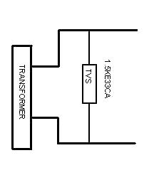
As shown, a maximum sine wave transformer out of 22Vrms can
be applied. The whistle/horn button of many traditional Lionel transformers
having compensating windings should NOT be used at full throttle, because
exceeding this value will result in Zener output clamping and possible loss of
protection.
The additional 3A series diodes increases the maximum
sinewave transformer output to 23Vrms:
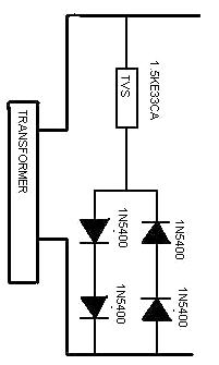
This is still not enough for full-throttle boost insertion,
but is the basis for an LED clamp indicator:
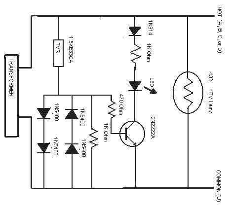
The resistors have a ½-watt rating; the LED, diodes and
NPN transistor are available from Radio Shack. When a milliampere-level
current flows through the Zener network, the 2N2222A switch turns on and the
LED is lit in a half-wave mode. At such current levels, there is insignificant
Zener heating and the change of LED state indicates the initiation of a clamp
mode at safe levels. If in addition the upper track feeder is connected to the
center rail, a positive-DC whistle/horn signal convention is sensed by this
LED state change, establishing the maximum permissible throttle setting
allowed on the Lionel transformer. Given a sufficient throttle output voltage,
the procedure tests that a clamp function will occur; at least for low “spike”
voltages.
Build A Simple Surge Suppressor
By
Frank E. Qualls
April, 99
The technical report you just read details what is
described as a simple transient voltage Surge Suppressor. This is not a
detailed step by step “How To” set of instructions for building this
device. The information provided here will give the Hi-Rail hobbyist basic
ideas for layout, packaging and parts sources which he can use. Surge
protection can be had by simply using a single 33-volt Bi-directional
transient voltage suppressor in parallel with each transformer throttle as
shown in drawing number 1. The circuit shown in drawing number 2 with the four
added diodes is recommended because it uses the voltage suppressor breakdown
range to its greatest advantage. Two independent 18-volt load lamps with a
common ground can be added in parallel with each TVS for zeroing out the LED
meters on the Z-4000. Each of these lamps also serve as track power indicators
by illuminating due to transformer voltage and as short circuit indicators by
dimming or extinguishing when a short is present on its respective track. They
are shown in the following pictorial drawings, which depict the number 3
circuit’s project box Top Cover and Perforated Board layouts.
My layout tests have shown that when using the MTH Z-4000
it can be operated at full throttle without illuminating the LED clamp
indicator. However, the Lionel ZW illuminates the clamp indicator at 18-volt
throttle level when using the whistle/horn controller.
Parts List
Below are the part numbers and sources of the parts used to build a Surge
Suppressor.
1 Project Box, Hosfelt part number JAL-3, 4 1/8” x 2 ¾” x 1 9/16”.
1 Black Banana Plug with setscrew, Hosfelt part number BU-00245-0.
2 Red Banana Plugs with setscrew, Hosfelt part number BU-00245-2.
The other parts required for this project are determined
by which circuit you choose to build.
Please refer to the circuit drawings
for the other component part numbers, which are listed in each drawing. The
quantity of parts required would be doubled for transformers with dual
throttles, which require two common grounded independent circuits. Hosfelt
Electronics is a good economical source for all of the above parts and those
in the diagrams except for the Transient Voltage Suppressor.
Please call Hosfelt at 1-800-524-6464 to request a Catalog.
Some of the parts for this project are also available from Radio Shack.
Microsemi Bi-directional Transient Voltage Suppressor rated
at 33v at 1500 watts P/N 1.5KE33CAMSCT-ND. Available from Digi-Key
Electronics call 1-800-344-4539 to request a catalog. Quantity (2) Note: A
Digi-Key minimum order of $25.00 is required. Also available from Mouser
Electronics as General Semiconductor P/N 625-1.5KE33CA. Call Mouser at
1-800-346-6873 to request a catalog. Mouser requires no minimum order.
Micro miniature Pre-punched Perforated Board. Radio Shack P/N 276-1396
Miniature Lamp Screw Base. Radio Shack P/N 272-356. Quantity (2)
2 Number 432 Lamps 18volts @ 250 ma. 1 Red, 1 Green or 1 Amber Lamp.
Available from Local Hobby shops.
One 4 position barrier strip.
Top Cover Layout
and
Perforated Board Layout
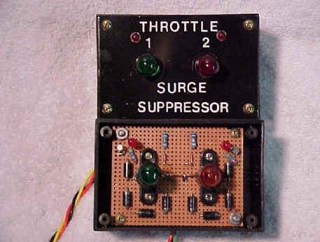
The above photo shows the Surge Suppressor top cover and
Perforated Board Layouts. The 1.5KE33CA TVS and barrier terminal strip for
connecting the Surge Suppressor to the transformer is underneath the
perforated board.
Simple Surge Suppression Protection
By
Frank E. Qualls

This photo shows the Simplest form of Surge
Suppressor protection one can have economically. The dual banana plug on the
left depicts the 1.5KE33CA TVS diode and a bayonet type lamp holder with
1.5-inches of wire and a number 1445 lamp attached. The banana plug is plugged
into both the plus or red and ground or black binding posts terminal outputs for
each throttle on the Z-4000. The number 1445 lamp provides a load for zeroing
out the Z-4000 voltage and ampere meters. The Radio Shack part numbers for the
dual banana plug shown is 274-717 and the bayonet type lamp holder shown is
272-355.
Editors Note: The circuits described have not been
approved or sanctioned by QSI as being acceptable protection for their
products. They have been designed with regard for the QSI T.R.E.O.S. published
specifications and technical reports. I think enough of our testing of the
Transient Voltage Suppressors and feel that this approach is sound to consider
as protection against voltage spikes for train electronics to have chosen it.
QSI, and PowerGuard are trademarks of QSI, Inc. Lionel ZW
is a trademark of Lionel L.L.C. MTH, Z-4000 and Z-750 are trademarks of Mike’s
Train House, Inc. All other trademarks are the property of their respective
owners.
Top of Page
What is Hugo's universal frog ? I want to run
both HiRail (3-rail) and 0-scale (2-rail) cars on my layout, so I had to make
some modifications to the 3-rail-turnouts ! One possibility is shown in the
picture.
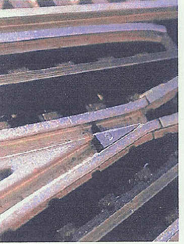
On a ATLAS O turnout ( 072) I have made a small slot in the
bottom of the frog parallel with the ties, then I made a small steel triangle
with a hole in the middle. The top-surface of the triangle matches the top of
the rails in the frog. A THROW BAR, between the ties, is connected to the
triangle by a rivet through the slot in the frog bottom. Now by moving this
THROW BAR the triangle will move from one side to the other and guide the wheel
on the right side of the FROG POINT. The wheel will be supported all the time,
so there will be no derailment and no rough riding through the turnout ! Note
that the GUARD RAILS are no longer necessary and I keep them only because the
turnout looks better with them !
Remarks:
1) If you want to run 2-rail Locomotives through this turnout,
you must cut the connection between the two running rails ( inside the 9th tie
from the front, or you will have a short between the running rails ! ( I just
drilled a small hole, from below, in the tie under the SWITCH RAIL and checked
that the connection was cut ! ) Then you must wire the turnout, as if it was a
2-rail turnout ! No HiRail cars with uninsulated wheels at the same time !!!!!
2) The 2-rail wheel sets has a bigger distance between the
wheels (flanges) - the so called "BACK to BACK of FLANGES" - measure (
NMRA S-4 Wheel Standard "B" = 1.118" (28.4 mm)), this means that
the GUARD RAILS in a 3-rail-turnout ( for smaller back to back measure ) will
not guide the wheel flange on the right side of the FROG POINT and the car might
derail !
3) I only use a solid center rail where the track can not be
seen, otherwise I use my STUD-RAIL-SYSTEM with studs hidden in the ballast
between the ties and pick-up skies clipped on the rollers ! ( See Fred M. Dole's
Story and Photos page 98 to 101 in the December 1998 ( Run 162 ) issue of O
GAUGE RAILROADING ) This STUD SYSTEM gives me the best looking track possible
for the reliable and easy 3-rail-system ! ( THE SAME REASON WHY MARKLIN, THE WORLDS
BIGGEST TRAIN MANUFACTURER, USED IT FOR THEIR HO-TRAINS FOR ALMOST 50 YEARS
!!!!!!!!!)
4) I have tried other solutions "TONGUE SWITCH" in
the frog, "MOVING WING RAILS" etc., but I find the TRIANGLE to be the
easiest and most reliable type of UNIVERSAL FROG !
IF YOU WANT MORE INFORMATION - ASK IN OUR FORUM !
Regards, HUGO B. PALLESEN, TCA 67-1844
Top of Page
Radio Shack Unlimited
401 N.E. 38Th. St.
Fort Worth, Texas 76106
1 (800) 241-8742
Compiled by Frank
E. Qualls, DC Area Independent Hi-Railers, April, 1998 (Updated 1/01)
The current Radio Shack male/plug part number 274-152 and
female/receptacle part number 274-155 specified on all Independent Hi-Railers module drawings are no longer available from your local Radio Shack.
These parts were discontinued by the original equipment manufacturer
Molex about three years ago (1995).
Tandy Corporation headquartered in Fort Worth, Texas and the parent company to
Radio Shack had an industrial parts division known as Tandy Electronics. This
division sold electronic parts to vendors packaged in larger quantities than
normally available from the local Radio Shack.
Since Tandy Electronics is no longer in business their remaining
inventories of the connectors we use are now available in Fort Worth, Texas,
through their warehouse named Radio Shack
Unlimited. They are packed into individual packages, which
contain 5 connectors. The part numbers listed below are for the plug and
receptacle. These connectors are not
packaged with the male and female
terminal pins. These .125”
Diameter terminal pins have to be ordered separately using the part numbers
listed below. They are packed into
individual packages, which contain 25
terminal pins.
Please keep in mind that each connector has six
circuits and they are sold in packages of five connectors, which
require 30 male or female terminal pins.
Please be sure to calculate the correct number of terminal pins you will
need when placing your order.
Radio Shack Unlimited
Name
Plug/Male 11315785
1 pack of 5
@ $2.39
Receptacle/Female
11315793
1 pack of 5
@ $2.39
.125” Male Terminal Pin 11315827
1 pack of 25 @ $4.89
.125” Female Terminal Pin 11315835
1 pack of 25 @ $5.29
These
parts are only available through mail order purchasing. They can be ordered using a credit card at the following
telephone number: 1
(800) 241-8742. The current inventory
that Radio Shack Unlimited has of these connectors
is not known. Therefore, it would
be prudent for those who need them to place your connector orders as soon as
possible. Note: These connectors are still available as of 1/2001.
Top of Page